

Received: 22-Sep-2023, Manuscript No. GJEEE-23-114591; Editor assigned: 25-Sep-2023, Pre QC No. GJEEE-23-114591 (PQ); Reviewed: 09-Oct-2023, QC No. GJEEE-23-114591; Revised: 15-Jan-2024, Manuscript No. GJEEE-23-114591 (R); Published: 22-Jan-2024, DOI: 10.15651/GJEEE.24.3.017
During the last few decades, due to many advantages of DC microgrid with the incorporation of Renewable Energy Sources (RESs) has been progressively adopted around the world. I integrating RESs with the power infrastructure face significant challenges in terms of maintaining power stability. A control scheme to hold the DC-link voltage of DC microgrid with PV (Photovoltaic) array constant with the condition of changing the source of load and power generation is proposed in this thesis. A Simulink model is developed MATLAB platform by discussing and evaluating the mathematical modeling of each component. A MPPT algorithm is used to control the PV array voltage and to control the storage system during atmospheric change. The proposed model includes with end to end connection with converters and BESS (Battery Energy Storage System).
RESs, PV array, Maximum Power Tracking Techniques (MPPT), PI controller, DC-link voltage, DC microgrid, MATLAB/Simulink
In an effort to cut greenhouse gas emissions throughout the world, an increasing number of people are turning to environmentally friendly forms of energy. A further cause for concern is the ongoing depletion of fossil fuels, which occurs concurrently with an increase in the demand for electricity. Renewable Energy Sources (RESs) such as solar photovoltaic, wind turbines, biomass generators, and other similar technologies have been used over the last two decades to meet rising electricity demand while lowering greenhouse gas emissions (Qazi et al., 2019; Son et al., 2022; Mahmood et al., 2021). RESs have the potential to be more beneficial in developing countries due to the fact that new business models are being developed to promote them. These models replace the traditional paradigm of providing energy access by expanding grid infrastructure with one in which bottom-up customers can generate their own modern energy to provide services through off-grid units or communityscale mini grids (Ebeed and Aleem, 2021). Microgrids can be used to address the issues of increasing power demand, the need for more reliable, diverse, and pure power production, and the limitations of the conventional power grid (Ullah et al., 2021; Kumar et al., 2017).
A microgrid is a self-contained local energy grid that includes Renewable Energy Sources (RES), Energy Storage Systems (ESS), local loads, and a variety of modern technologies (Mahmood et al., 2021). Both AC and DC microgrids can be used to supply electrical power to loads. But DC microgrids are more preferable as it is more efficient, reliable and stable (Wang et al., 2021; Tan et al., 2021). Table 1 overviews a literature review of the DC microgrids (Bhosale, 2016; Cupelli et al., 2018; Mann, 2018; Zhang et al., 2015; Gil-gonzalez and Garces, 2019). Thus, to obtain a high and stable voltage from RESs, it is necessary to equip DC-DC boost converters and an Energy Storage System (ESS) with a DC-DC buck-boost converter that can control the storage system's charging and discharging current (Sivakumar et al., 2015; Kumar et al., 2021; Eghtedarpour et al., 2014; Roy et al., 2016). In (Ye et al., 2017; Rios et al., 2021; Iyer et al., 2021), a Dual Action Bridge (DAB)-based converter is used to overcome the complexity of multilevel 4 controllers. However, this DAB-based converter is not able to provide a satisfactory performance during the transient conditions of the DC microgrid.
| Method | Consideration | Limitations |
| Fuzzy logic controller | Balancing the load-generation mismatch. | Efficiency is not high. |
| Data-driven controller | Stabilizing the bus voltage under large perturbations from connection/disconnection of converters. | Does not consider accurate and analytical models, or exchange of information among converters. |
| PI controller |
Reduce the bus voltage variation in the microgrid and to utilize the storage devices optimally. | Synthetic inertia adds complexities in the system. |
| Data-driven model-free adaptive voltage control |
Controlling the interlinking converter to realize proportional power sharing between AC and DC microgrid. | Design of the controller is only based on input/output measurement data. |
| Passive PI controller | Asymptotically stabilizing in closed-loop for the boost DC-DC converter Converter. |
Integrate the PV systems with a distributed maximum power point tracking method. |
Table 1: Overviews a literature review of the DC microgrids.
The proposed renewable energy-based DC microgrid of the paper is organised as follows: Section II covers the design of microgrid and modelling. Then, the corresponding simulation result and discussion of the dc microgrid are concerned in section III. Finally, the conclusion of this presented work is presented in section IV.
Proposed Microgridand Modelling
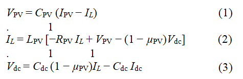
Dynamic model of the solar PV Unit with DC-DC boost converter: According to Figure 1, the dynamic model of the solar photovoltaic system connected to the DC/DC boost converter can be described with the following differential equation:

Figure 1: The proposed DC-microgrid structure.
Control of DC-DC boost converter of PV array for maximum power extraction: Various PV array parameters (1Soltech 1STH-215-P) consist of one string and five modules connected to the sequence shown in Table I. The P-V characteristic is non-linear and there is only one operating point where the maximum power for one specific irradiation and temperature condition is shown in Figure 2.

Figure 2: P-V characteristics of PV array for temperature (25°C).
By using the DC-DC boost converter between the PV array and the load bus, load impedance is matched to the source impedance to receive maximum power from the PV array. Impedance matching is accomplished by altering the duty cycle ratio of the DC-DC boost converter. The literature proposes various maximum power monitoring algorithms that assess the converter's duty cycle ratio. Incremental conductance algorithm is used to extract the maximum power from PV array (Tables 2 and 3).
| Parameters | Value |
|---|---|
| Pmax | 213.15V |
| VMPP | 29V |
| IMPP | 7.35A |
| VOC | 36.3 |
| ISC | 7.84A |
Table 2: Parameters of PV array (1Soltech 1STH-215-P).
| Parameters | Value |
|---|---|
| Cpv | 100 µF |
| L | 5 mH |
| Cdc | 3300 µF |
| fsw | 5000 Hz |
Table 3: Parameters of DC-DC boost converter.
Steps of Incremental Conductance MPPT Algorithm
Load Power Control
In this research, constant power load and constant resistive load combinations are taken into account and are regulated only by the user.
DC-DC Bidirectional Battery Converter Power for Regulation of Load-Bus Voltage
In Table 3, various parameters of a bidirectional DC-DC converter and battery are shown the power balance between the PV array under MPPT, battery and load are maintained by the battery's charging/discharging. The battery charging/discharging order is extracted from the controller and is carried out by the bidirectional DC-DC converter (Table 4).
| Parameters | Value |
| Cb | 1000 µF |
| Lb | 0.5 mH |
| Cdc | 3300 µF |
| fsw | 5000 Hz |
Table 4: Parameters of PV array (1Soltech 1STH-215-P).
Battery Unit
In various operating conditions, the main goal of the BCU is to retain the DC-link voltage constant at the desired reference value. Through the usage of a battery-operated by a bidirectional buck-boost converter, this purpose can be achieved. In such converters, such as bidirectional buck-boost converters, the battery voltage level may be selected to be lower than the desired reference value. During day and night, the buck-boost converter's control function is to modify, observe and monitor the battery activity. Depending on the BCU control action, the battery modes of operation can be charging, discharging or standby. An inductor is used on the side of the battery to minimize the battery current ripple which in turn enhances battery performance and extends its lifespan. The BCU consists of two cascaded PI controllers. By comparing the real DC-bus voltage (Vdc) with the appropriate reference value (Vdc ref), the first is responsible for producing the reference signal of the desired battery current (Ibat ref). The real battery current is measured and compared with the previously defined reference signal in the second PI-controller. The output of the controller is the buck-boost converter duty-cycle that generates the necessary switching pulses of the converter switches compared to a carrier signal. The battery's operating modes are mainly based on the DCbus voltage level that is correlated with the required reference value. The DC-bus voltage in the charging mode is greater than reference voltage. When the power generated from the PV array is greater than the load requirement, this mode begins. The battery, therefore, is in charging mode. The DC-bus voltage is less than the necessary voltage in the discharging mode. This mode occurs when the power produced from the PV array is insufficient to supply the load. In order to resolve the shortfall, the battery discharges in this way. Parameters of the Lithium-ion battery are shown in Table 5.
| Parameters | Value |
| Vnom | 24V |
| Ah capacity | 50 Ah |
| Initial SOC | 45% |
Table 5: Parameter of lithium ion battery.
Simulation and Derived Result
The proposed control strategy is implemented on PV/ battery standalone DC power system having resistive load of 6Ω and constant power load of 293.4 watt for a solar irradiation of 300 W/m2, 500 W/m2, 1000 W/m2 and 300 W/m2. Initial value of duty cycle for DC-DC boost converter is taken as 0.5 and MPPT is turned on at 0.05 sec. From 0 sec to 4 sec resistive loads is connected and irradiation is kept at 0 W/m2, the power generation from the PV array is 0 watt. During this period the load demand is 532.7 watt which is less than the generation hence battery controller is activated and excess power is fed to the battery and DC-load bus voltage is maintained at 48.07 V. During 4 sec to 8 sec, irradiation is kept at 300 W/m2 required load power is 347.6 watt but this time generated solar power is 322.2 watt that’s why battery is still in discharging mode. During 8 sec to 12 sec, irradiation is kept at 500 W/m2 and required load power is 532.6 watt and generation power is 540.2 watt i.e. battery starts to charge itself through DC-DC bidirectional converter.
During 12 sec to 16 sec irradiation rises to 1000 G.W/m2 and required load power is fulfilled by generation and remaining power flows to battery storage system. During 16 sec to 20 sec, irradiance falls at 300 G.W/m2 and total generation is now less than the required load power so battery starts to discharge again. Thus, controller during the whole shown period controls the charging and discharging process of the battery storage system in a controlled way when the generation power is greater than required load power battery starts to store the surplus power and when the generation power is producing less the load is fed by the power from the battery storage. These phenomena are shown in Figures 3-7 respectively.

Figure 3: Solar irradiance.

Figure 4: Solar PV power.

Figure 5: Load power.

Figure 6: Battery power.

Figure 7: DC link voltage.
This paper has proposed a control scheme to maintain the DC-link voltage constant with the condition of changing of load and power generation source. A model is built by using the mathematical modelling of each component has been discussed and analysed here. As PV array is used here as generation source which has nonlinear I-V curve and the output power of PV array depends on environmental factors, such as solar irradiation and temperature. There is a point on I-V, P-V characteristic curve of PV array known as Maximum Power Point (MPP) from which maximum output power can be calculated. Position of MPP shifts with environmental change. For this purpose, a local controller is used with DC-DC boost converter which can monitor difference between atmospheric conditions and the reference current and voltage. PI controller scheme is used here to control the battery storage system along with DC-DC bidirectional converter. From simulation result it can be seen that DC-link voltage is stabled through controller. This scenario has been done during changes of solar irradiance and changes of load is also considered here to check if the controller can manage the stability even if the situation does not remain in favourable situation.
This proposed controller is proved to be efficient to maintain the voltage stability regardless variation in load or in atmospheric condition.
[Crossref] [Google Scholar] [PubMed]
[Crossref]
[Crossref] [Google Scholar] [PubMed]